Overview of RiverFlow2D
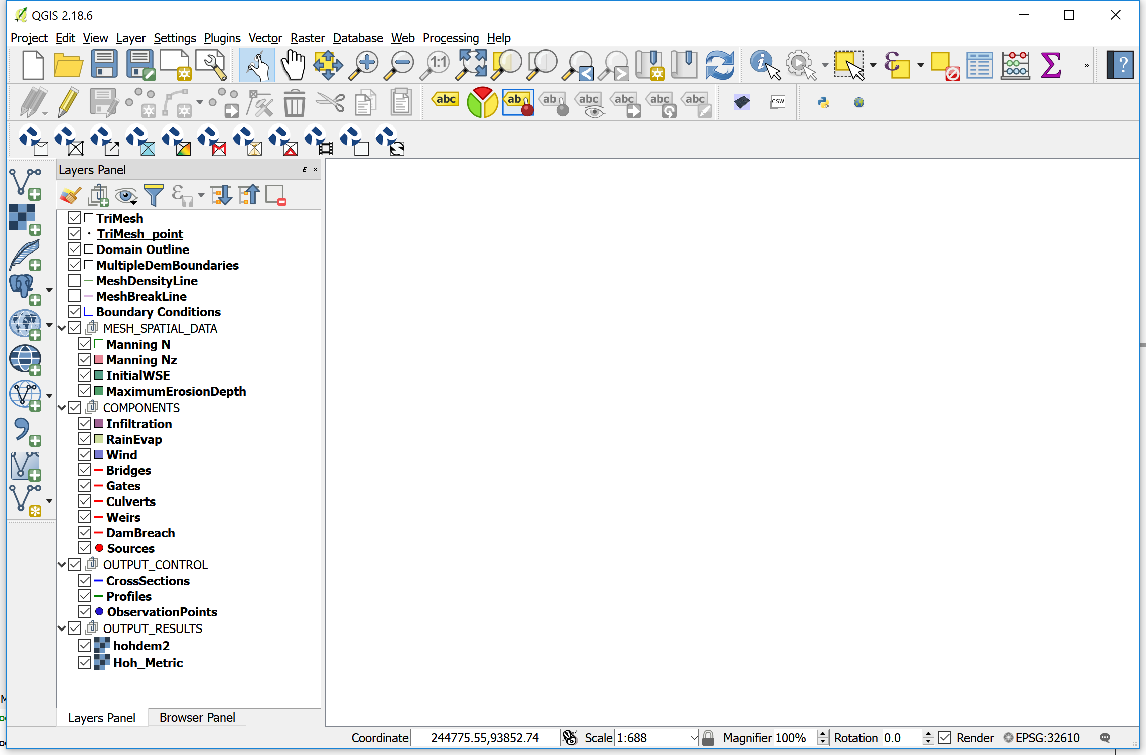
When you create a new RiverFlow2D project in QGIS, the plug-in creates a number of empty layers, each one with an specific purpose, and associated with particular components or modules. The standard set includes the layers depicted in Figure. Description of each layer is included in Table.
**Content**
**Content**
- TriMesh Polygon Contains the mesh triangular cells. It is automatically created by the mesh generation program.
- Domain Outline Polygon Container for the required external polygon that defines the extent of the modeling area. It can also include internal polygons that represent impermeable islands or other obstacles that will not contain cells. Each polygon has a CellSize attribute that controls the approximate triangle size desired for the generated mesh.
- MultipleDemBoundaries Polygon It is used to enter polygons that define areas with different terrain elevation data sets. You can associate each polygon to a different raster layer containing a terrain elevation model.
- MeshDensityLine Line It is used to enter polylines along which the mesh generation program will refine the mesh according to each polyline CellSize attribute. The lines do not force the mesh generator to create nodes along the lines. In this sense, they act as soft breaklines.
- MeshBreakLine Line It is used to enter polylines along which the mesh generation program will refine the mesh according to each polyline CellSize attribute. The lines do force the mesh generator to create nodes along the lines. Therefore, they act as hard breaklines.
- Boundary Conditions Polygon Container for polygons that define the model open boundaries, either inflow or outflow. All the boundary cells laying inside these polygons will be open boundary cells.
- MESH_SPATIAL_DATA
- Multiple DEM Boundaries Polygon Container for polygons over which different elevation rasters (e.g. DEMs) will be used to interpolate elevations to the cells.
- Manning N Polygon Defines areas of different Manning's n.
- Manning Nz Polygon Accepts polygons associated to files that contain tables of Manning's n as a function of depth.
- InitialWSE Polygon Container for areas of initial Water Surface Elevations (WSE).
- MaximumErosionDepth Polygon Container for polygons with Maximum Erosion Depth (MED) attribute. When using the Sediment Transport ST module, the model will not allow erosion to reduce the bed elevation below the initial bed elevation minus MED.
- COMPONENTS
- Infiltration Polygon Defines areas of different Infiltration parameters.
- RainEvap Polygon Container for areas associated with a rainfall intensity and evaporation.
- Wind Polygon Defines areas associated with a wind velocity time series that will be used in the model to calculate the wind stress on the water surface.
- Bridges Line Includes polylines defining bridges. Each entity will have specific data that characterize the bridge cross section. Also the lines will act as hard breaklines.
- Gates Line Includes polylines defining gates. Each entity will have specific data that characterizes the gate including gate aperture table. Also each line will act as a hard breakline.
- Culverts Line Contains lines that connect two points in the modeling area with culverts. The model will calculate the culvert discharge depending on the given data, and transfers discharge from culvert the inlet cell to the culvert outlet cell.
- Weirs Line Container for polylines defining weirs. Each entity will have specific data that characterizes the weir. The line will act as a hard breakline.
- DamBreach Line Contains polylines that represent dam or levees in plan. They allow the model to calculate the discharge through levee or dam breaches.
- Sources Point Container for point sources or sinks. Source data includes a time series of discharge vs. time. When using the Pollutant Transport PL Module, the data must include concentrations for each pollutant in addition to the discharge. Sinks are defined by negative discharges.
- OilSpills Point Container for spill locations within the mesh. Each spill point needs data to define the spill volume, and other parameters required to simulate the oil trajectory and behavior based on existing results from a hydrodynamic run.
- Piers Point Container for bridge pier locations. Piers are used to enter data that will allow the model to compute scour around bridge piers.
- Abutments Line Container for bridge abutment locations. Abutments are used to enter data that will allow the model to compute scour around bridge abutments.
- StormDrain Point Container to indicate flow exchange points between the surface water with the storm drain network of a EPA-SWMM model.
- OUTPUT_CONTROL
- CrossSections Line Container for lines that define cross sections where the model will write results including discharge for each report interval.
- Profiles Line Defines profiles where the model will write in text files results for each report interval.
- Observation Points Point Container for locations where the model will write results each report interval.
- OUTPUT_RESULTS Group that include layers with model results that will be incorporated by the program when creating specific graphics with model results.
- RiverFlow2D layers.